
-edible zone-
For use as an MC step-up.
*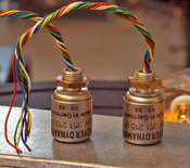 Beyer Dynamic TR / BV 351 215 006 microphone transformers. I picked this
pair up on Ebay (used ) for ~ $30.00 usd or thereabouts.
Beyer Dynamic TR / BV 351 215 006 microphone transformers. I picked this
pair up on Ebay (used ) for ~ $30.00 usd or thereabouts.
* (click thumbnail for full image size)
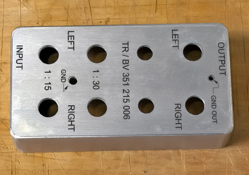
Above: the all important map. Where to solder what.
*


*above: the project case. For these small Beyer Dynamic cans, I can use a case with compact dimensions. Hammond #1590B. This is die-cast aluminum in two pieces. The lid is assembled to the box by four machine screws. Hammond project cases are available in a wide variety of sizes and are affordable. This case cost ~ $5.00 usd. Fwiw, I can't remember what I paid. I found it while browsing through the electronics parts in at a local Fry's. They are available online cheaper, but then you pay shipping to get it home.
* All parts modeled full scale in Rhino 3D.This way I can get a precise
vision of the proposed project will look like before I start cutting
materials.
All parts modeled full scale in Rhino 3D.This way I can get a precise
vision of the proposed project will look like before I start cutting
materials.
*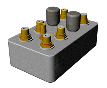 Here's a render of the proposed layout.
* After some thought, I chose a "top-loader" layout because all the
parts would fit the case, and then I chose this just for subjective
aesthetics. If using different sized transformers, I might choose a
different arrangement....perhaps with the rca jacks mounted to the sides
of the case. But these Beyer Dynamic cans are rather tiny and afford the
layout in the renders.
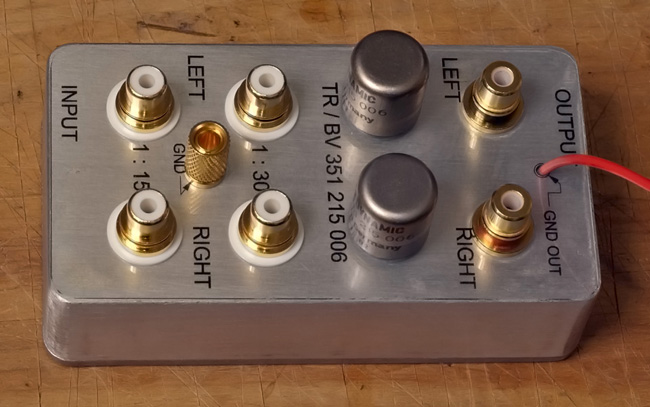
This box will offer two different voltage
step-ups. 1:15 and 1:30. This means that if the signal coming off the
cartridge is .2mv, it will be 3.0 mv when using the 1:15 tap, and 6.0mv
if using the 1:30 tap.
I have noticed that sometimes the method
of selecting between a high and low setting on step up transformers is
chosen by means of a switch that selects between the turns ratios.
However. I chose to use four RCA inputs because by doing so I could
avoid sending the very tiny signal voltage coming off the MC phono
cartridge through a selector switch before it reaches the transformer.
When possible, I want to keep the signal path as simple and short as is
possible. But then, again, I'm just an idiot off his leash. ;^)
* This is the drill map. Drawn and then printed full scale. .
* Things needed. The project case. An automatic center-punch. The drill
map. And some spray-on adhesive to fix the map to the case. The Elmers's
adhesive, seen in the photo, dries quickly and has adhesion adequate for
this task.
Things needed. The project case. An automatic center-punch. The drill
map. And some spray-on adhesive to fix the map to the case. The Elmers's
adhesive, seen in the photo, dries quickly and has adhesion adequate for
this task.
* The drill map printed and cut. For this task, I used presentation matte
ink jet paper by Canon. This isn't quite photo grade paper but is
stiffer than plain paper and will work well for placing the drilled
holes. I got it in letter size 50 sheets for $5.00 usd.
The drill map printed and cut. For this task, I used presentation matte
ink jet paper by Canon. This isn't quite photo grade paper but is
stiffer than plain paper and will work well for placing the drilled
holes. I got it in letter size 50 sheets for $5.00 usd.
* After glue.
*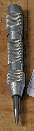 Here's my Starrett 'automatic center-punch'. It has a spring loaded trip
hammer that is actuated by simply pushing down on the handle end while
the business end, with the point, is centered on the mark. It makes a
nice clean punch mark that is easy to find on the drill press. A nice
tool to have around when you're laying out and drilling holes into
metal. (old machinist's trick ;-)
Here's my Starrett 'automatic center-punch'. It has a spring loaded trip
hammer that is actuated by simply pushing down on the handle end while
the business end, with the point, is centered on the mark. It makes a
nice clean punch mark that is easy to find on the drill press. A nice
tool to have around when you're laying out and drilling holes into
metal. (old machinist's trick ;-)
* The case after drilling,..... but with the template still in place. It
appears that I hit my marks close enough for this project. To remove
this template, is squirted some Ronson lighter fluid over the paper.
Enough to soak through. Then, after a few minutes, the template lifted
off cleanly.
The case after drilling,..... but with the template still in place. It
appears that I hit my marks close enough for this project. To remove
this template, is squirted some Ronson lighter fluid over the paper.
Enough to soak through. Then, after a few minutes, the template lifted
off cleanly.
* The drilled box after deburr and clean-up. For the external finish I
considered paint, but opted for a "brushed aluminum" finish instead. To
get that I used a 6 inch long auto body sanding board with 120 grit
sandpaper. I sanded all external surfaces on the box. I chose not to
sand the lid.
The drilled box after deburr and clean-up. For the external finish I
considered paint, but opted for a "brushed aluminum" finish instead. To
get that I used a 6 inch long auto body sanding board with 120 grit
sandpaper. I sanded all external surfaces on the box. I chose not to
sand the lid.
* Prior to assembly, this view shows the individual parts to be assembled
into the project box. Six different gold plated RCA jacks. One gold
plated ground stud that will accept both spade and banana connectors.
Notice the one foot length of interconnect cable forming a circle around
some of the components? That is Cardas twin link copper litz. Cardas #
5190. This is 23.5 awg conductor shielded and in teflon dialectric.
Pretty good stuff. I'll use that piece to make the two outputs that lead
from the SUT into the phono stage.
Prior to assembly, this view shows the individual parts to be assembled
into the project box. Six different gold plated RCA jacks. One gold
plated ground stud that will accept both spade and banana connectors.
Notice the one foot length of interconnect cable forming a circle around
some of the components? That is Cardas twin link copper litz. Cardas #
5190. This is 23.5 awg conductor shielded and in teflon dialectric.
Pretty good stuff. I'll use that piece to make the two outputs that lead
from the SUT into the phono stage.
*
But wait, there needs to be markers to instruct the user where to plug in the phono cable plugs and ground strap. For a label pattern, I used inkjet transparent media as an overlay. This particular media has an adhesive on its backside. After trim, and before application, just remove the substrate layer, then carefully lay the transparency over the part to line up with the drilled hole pattern. First try, I missed. Second try looks closer and I think will appear good after the box is populated with its rca jacks, ground stud and the tranny cans.
*
- There it is. All that remains is to solder the wires from the trannies to the individual rca jacks and ground stud. Then I'll have to put some feet on the bottom cover.
Done. It took a while to solder the individual tranny wires to their respective tags on the RCA jacks and ground post. There needed to be some care. The wires are very fine gage. The insulation is fine. The space inside that small project box is confined. Care must be taken. But all went well. All solder joints hold and deliver signal. Victory.
* Action shot! The BD cans deliver signal to the Wright WPP100C phono
preamp. Also on this photo my very short output IC's can be seen. These
are the above noted Cardas 23.5 awg twin-link copper litz conductors.
I've soldered some old(but good) AudioQuest RCA phono plugs to this new
wire. This gives me 6 inch long IC's between SUT and phono stage. That
should keep the capacitance low. Background, upper left, the Sowter SUT
box, supplied by George Wright, that I had been using previously.
Action shot! The BD cans deliver signal to the Wright WPP100C phono
preamp. Also on this photo my very short output IC's can be seen. These
are the above noted Cardas 23.5 awg twin-link copper litz conductors.
I've soldered some old(but good) AudioQuest RCA phono plugs to this new
wire. This gives me 6 inch long IC's between SUT and phono stage. That
should keep the capacitance low. Background, upper left, the Sowter SUT
box, supplied by George Wright, that I had been using previously.
Some technical details.
The MC cartridge being stepped up is
a Shelter 501 type II that is currently mounted to my TD124. The Shelter
is carried by a Zeta tonearm with Incognito/VdH silver phono cables. I'm
using the 1:15 tap on the Beyer Dynamics to multiply the .4mv signal up
to ~6mv output. This will be an acceptable voltage output for feeding
the phono stage.
But what about cartridge loading? The Shelter
has an internal resistance of 10 ohms. There is this rule of thumb often
quoted by the audio press about MC step ups. Multiply internal
resistance by 10 to find optimal loading. In this case, if rule of thumb
holds true, the target would be 100 ohms of load.
* If I use the 1:15 tap and calculate as follows:
47K/15^2 = 209
ohms
209 ohms. Less than half the load it was seeing with the
1:10 Sowter step ups. But twice the optimal "rule of thumb" load.
One other thing I had anticipated is that the gain on the Wright
WPP100C phono preamp would need to be turned down a bit to keep volume
levels the same. And this is the case. I now have the gain pots set to
3:00 o'clock. Where before, with the 1:10 Sowters, I had it at 4:00
o'clock.
* But how does this sound? The interesting thing is I
thought that by halving the load that there would be some audible effect
with regard to frequency extension and / or perceived warmth/coolness or
otherwise sonic coloring. Not really. Frequency extension seems similar
at either end. There is a bit more of inner detail being heard with the
Beyer Dynamic cans. Or perhaps it is a different emphasis toward
instruments. For instance on Brubeck's "Time In" album, the Morello's
Cymbals have "more metal" in the timbre and ring than with the Sowters.
And I perceive this as a positive.
I'm still determining of there
is any rolling off at the very top. The upper regions at the extreme end
of (my) human hearing. The Sowters may offer more detail up there.
Probably, that does not matter to me. I should add that this observation
is not meant to infer that there is any loss in upper frequency
extension. Nothing remarkable other than fractional differences between
the Sowter and BD transformers. Either one has good upper frequency
extension in combination with the phono stage in use.
There is an
increase in punch from the lower frequency regions. Call it a good sense
of the visceral on rhythm and drive. More than before. Good atmosphere.
Good sparkle. From Beethoven string quartets, to Pink Floyd, a good
listen.
Then I tried the BD SUT with an Ortofon Jubilee
cartridge.
*
That cartridge has 5 ohms internal resistance with .345 µv output.
The Ortofon seemed happiest and most dynamic on the 1:30 tap.
Let's try the rule of thumb on the Ortofon: 5 ohms internal resistance x
10 = 50 ohms for an optimal load. To calc load: 47k / 30²=52.2 ohms
load. Very near optimal. 1:30 is a good turns ratio for this Ortofon.
With that in mind, I can't say that the BD cans transformed the Jubilee
into something different. Pretty much, it is the same MC cartridge I've
known but with slightly more dynamic punch. That much is notable.
The Shelter 501-II and the BD step up on the 1:15 tap. The 501-II
has an output of .4 mv and in internal resistance of 10 ohms. While the
Shelter did sound good with this step up, and after long term listening,
I decided that the mixture seemed a little "hot". A tad too much gain. A
bit too edgy. Prone to listener fatigue. Not quite right. But the
Shelter seemed more at ease and 'right' while using the 1:10 Sowter SUT.
Different step ups for different cartridges.
The DL-103R liked
the 1:15 tap on the BD sut. This combination gave the Denon lomc
cartridge a bit more force and speed than what the Denon seemed like
with the 1:10 Sowter step up. BD and Denon it is!
(Aside: The BD
sut seemed equally at home using either the Wright phono preamp or the
Hagerman Trumpet phono stage. While the Trumpet delivers a more refined
sound than does the Wright regardless which SUT is in use. This goes for
either stage using mm phono cartridges. )
* (click thumbnail for full size image)
Associated Equipment:
Turntables:
- Thorens TD124, Zeta tonearm / vdH silver wire with silk jacket organized in an incognito harness (with a few repairs carried out by yours truly)
- Thorens TD150 mk II (R7-2) Graham 2.2 tonearm, Ortofon MC Jubilee cartridge, Cardas Phono cable.
Phono stage:
- Wright WPP100C tubed phono preamp
- Hagerman Trumpet 47 kohms phono stage
Amplifier: Classe' CAP 151 integrated (150 wpc into 8 ohms)
Speakers: NHT 2.9 (4-2ay floor standing towers with 10 inch side-firing bass drivers)
Cables: Canare 4S-11 in Bi-Wire configuration and terminated with silver spades.
Interconnects:
- silver conductors by Garth Phillipe from the Wright stage output into the Classe' integrated amp.
- Cardas 23.5 awg copper litz conductors termined with AQ rca plugs at the output side of the BD SUT