-edible zone-
-- Note: This page will document subchassis rigidity of the TD150 by measuring for deflection near the bearing when its own platters are fitted. Then the same test will be given to a TD160 subchassis for comparison.
--
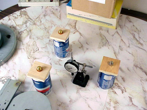
-- Lacking a professional inspection grade granite surface plate, and also precision blocks to mount the subchassis into position for this test, I improvise with: Pepsi cans, the plywood squares , and brass acorn nuts.
-- The three mounting points are located to support the subchassis
next to the spring grommet holes. The dial indicator is located next to
the platter bearing and will read the amount of deflection to the
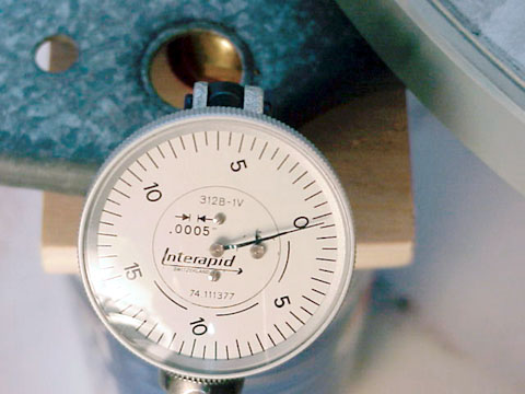
nearest .0005 inches.
-- Pepsi cans are full. Wood squares are
1/2 inch thick baltic birch plywood. Acorn nuts serve as the
contact points. Copper washers were used as shims under two of the acorn
nuts to level the subchassis frame. I checked this method for
repeatability several times with no readable variation in deflection
measures.
--The test begins with the TD150 subchassis
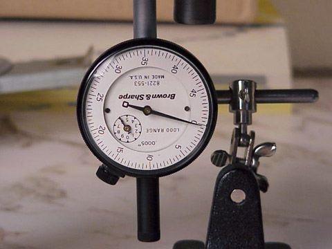
* (click thumbnail for full image), Close-up view of the indicator reading
under zero load.
(click thumbnail for full image), Close-up view of the indicator reading
under zero load.
* The TD150 subchassis frame set up on the three points. Indicator
is zeroed. Waiting for the inner platter.
The TD150 subchassis frame set up on the three points. Indicator
is zeroed. Waiting for the inner platter.
* Loaded with inner platter. Deflection reading: .0025 inches.
* Close-up of the indicator reading the load with inner platter mounted.
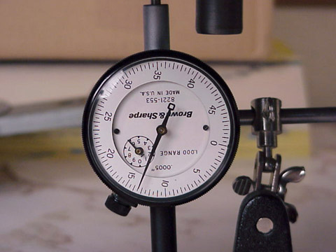
* Loaded with both inner and outer platters (7 lbs). Reading is
nearly .007 inches.
Loaded with both inner and outer platters (7 lbs). Reading is
nearly .007 inches.
* Closeup of indicator reading deflection under the load of both platters.
* Indicator read after both platters are removed. The needle repeats
back to zero. This process proved to be repeatable within the
accuracy of this dial indicator which reads to the nearest .0005 inches.
Indicator read after both platters are removed. The needle repeats
back to zero. This process proved to be repeatable within the
accuracy of this dial indicator which reads to the nearest .0005 inches.
-- TD160 Subchassis
* The TD160 subchassis and indicator are ready . The indicator is
positioned near the bearing and set to zero.
The TD160 subchassis and indicator are ready . The indicator is
positioned near the bearing and set to zero.
* Close-up of the indicator dial set to zero.
* With inner platter installed. The indicator now reads .0035 inches
of subchassis deflection near the bearing.
With inner platter installed. The indicator now reads .0035 inches
of subchassis deflection near the bearing.
* Close up of the indicator reading with inner platter mounted.
* Both inner and outer platters installed. Indicator read: .0135
inches.
Both inner and outer platters installed. Indicator read: .0135
inches.
* Close-up of the read .
* End of test. Both platters carefully removed and indicator needle
returns to zero. A successful test.
End of test. Both platters carefully removed and indicator needle
returns to zero. A successful test.
_______________________________________horizontal rule
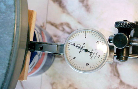
-- What about this setup? Is it valid? It would be useful to test the "full" Pepsi cans and plywood squares for compression before getting too excited about the indicator readings taken above. What follows is an effort to measure how much compression/deformation the cans and blocks take on under the loads of the above test.
*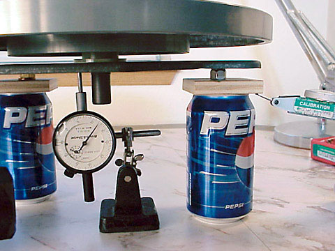
--Above: there are two smaller finger indicators, on either side of the large indicator in the center, taking the read at the support structures (full Pepsi cans) to check for any needle movement. Should the cans themselves show deflection under load these indicators would show it.
* Note we check both on top and underneath the wood blocks for any
deflection under load.
Note we check both on top and underneath the wood blocks for any
deflection under load.
* The largest indicator reading in these two areas were from the top of
the wood block. Just slightly less than .0005 inches....max.
The largest indicator reading in these two areas were from the top of
the wood block. Just slightly less than .0005 inches....max.
*
--The Pepsi cans (full) and plywood squares do compress somewhat under the loads in this test. This amount of compression is less than 0.4% of the chassis frame defection reading taken with the center indicator. I'll include this as error, allowing myself a 10% error margin under the conditions of this improvised test method.
-- To summarize: the TD150 deflected .007 inches under the load of its own platter system. The TD160 deflected .0135 inches! Both models use the same platters and bearing.
-- What's the point....?
The goals are to achieve 1) precise
tonearm alignment and 2) the most constant platter speed.
Tonearm alignment: If, when under load, the subchassis can flex a small
amount then both parallel and distance relationships between the tonearm
and platter bearing will be in motion. A loss in the precision of your
tonearm alignment.
Constant platter speed. If the subchassis can
flex dynamically while the platter is in motion, the distance between
platter and motor pulley can also be in motion. Consider also the
flexible belt which will stretch and contract as the distance between
platter and pulley changes. The AC synchronous motor will maintain its
constant speed but the belt length will stretch and contract. Platter
speed accelerates and decelerates (minutely). Platter speed becomes less
constant. A wow/flutter test should be in order to test the
validity of this supposition.
My goal is to find a way to have
absolute rigidity of the subchassis frame under load. Similar to a non
suspended table with a massive base. Zero movement of the base. Yet I
want to have the benefit of isolation provided by the spring suspension
of this table.
Btw, has anyone taken a close look at The TD125 and TD126 floating subchassis? Those are far more massive than these models. I suspect that neither of those will show any deflection under the load of their own platter system. Of course those models were quite a bit more expensive to purchase back in the day, and also to buy second hand today.