edible zone
Technics SP10, SP10mkII and mkIII Gallery
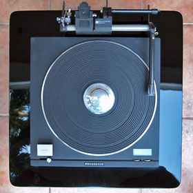 Troporobo's SP 10 ( PI )
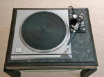 Peter
F...... SP10 mkII (Australia)
Peter
F...... SP10 mkII (Australia)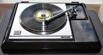 Ken McCarty's sp-10 mkIII (USA)
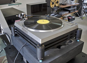 User510's SP-10 mkII (USA)
_______________________________________horizontal rule
The Mule: An SP10 mkII Project Page
_____________________________________horizontal rule
Links:
https://www.vinylengine.com/library/technics/sp10.shtml
Mounting Templates:
sp10 mkII mtg. template - in pdf format requires acrobat reader - - units are metric the dwg is not to scale-
Parts Lists and drawings:
Capacitors and trimmers to replace (pdf)
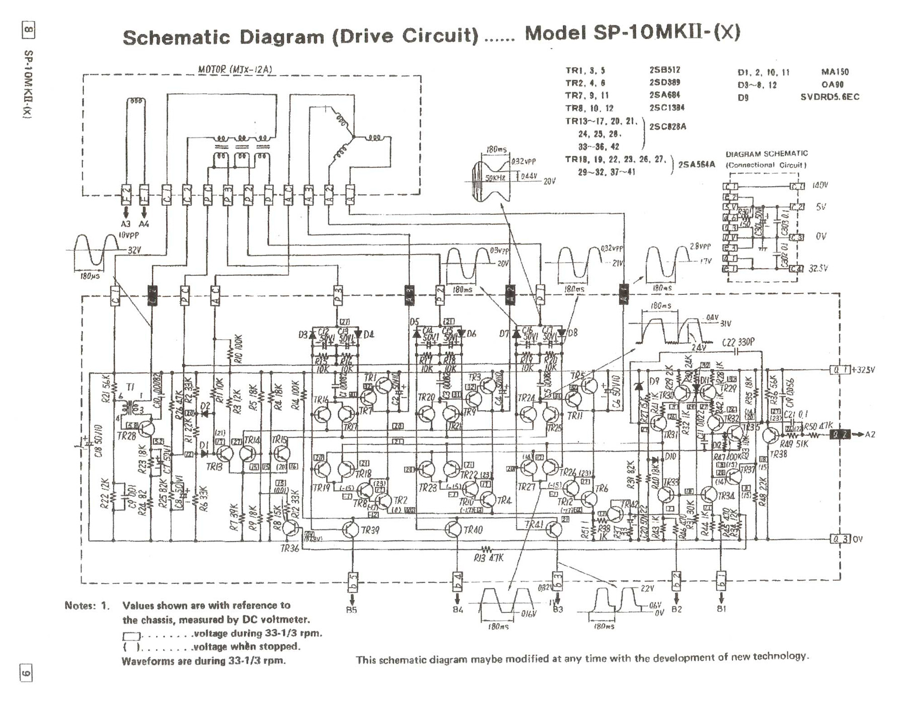 mkII drive circuit diagram (large jpeg image)
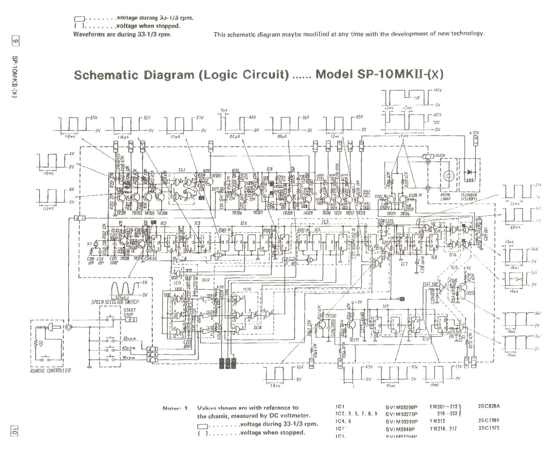 mkII logic circuit diagram (large jpeg image)
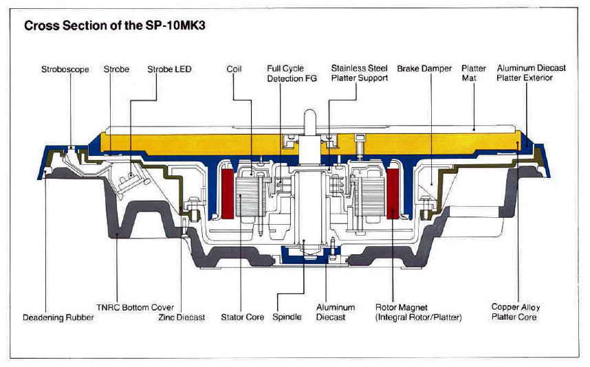 SP10 mk3 cross section dwg. Click thumbnail for full size image.
Notes on the speed regulation:
Thanks to The Vinyl Engine, we
have access to good copies of the service manual to assist (heavily) in
this project. I'll try to paraphrase and condense the explanation of the
various circuits that regulate platter speed on this interesting record
player.
1) First there is quartz oscillator that generates a
reference signal. The reference signal is split by a frequency divider
into the appropriate frequency for each of the three available speeds.
And this speed information is stored in digital memory.
2) There
is a strobe logic circuit that is used to flash the neon strobe bulb.
3) Frequency Generator.
It says that the Frequency Generator is
integrated with the platter drive motor and converts platter rotation
speed into a frequency. And the output of this frequency is fed to the
speed and phase control circuits.
4) Phase Control Circuit
The
phase control circuit detects phase difference between a reference
signal (see item #1) and the frequency generator signal (item #3) and
generates a control voltage. So between the reference signal, the
frequency generator and the phase control circuit the rotation of the
platter is "locked" to the reference signal.
5) Speed Control
Circuit
Here it describes a "sample hold" circuit that converts
output of the frequency generator into an electrical voltage. This is
the control voltage which maintains platter rotation speed.
(Btw,
we already knew that the motor was brushless DC, right?! DC motors are
speed-controlled by voltage. More volts = more rpms....more or less.)
6) Drive Circuit
Here I just quote the service manual.
"Two control signals are composed and applied to the drive circuit to
maintain a forward motor rotation. The drive circuit supplies full wave
drive current doubling current efficiency. It supplies drive current in
both directions for a symmetrical rotation in either a forward or
reverse direction."
7) Start/stop Circuit
Hit the on button
and the circuit starts the platter rotation. hit it again and a reverse
drive plus mechanical brake is applied.
8) Mechanical Brake
Actuating Circuit.
Here it describes a circuit that operates a
solenoid that pushes a brake shoe against the platter. And this is
working together with the above noted start/stop circuit. There's more
but you get the idea.
There you go. Tech-geek translated into
English courtesy of this idiot at The Analog Dept.